

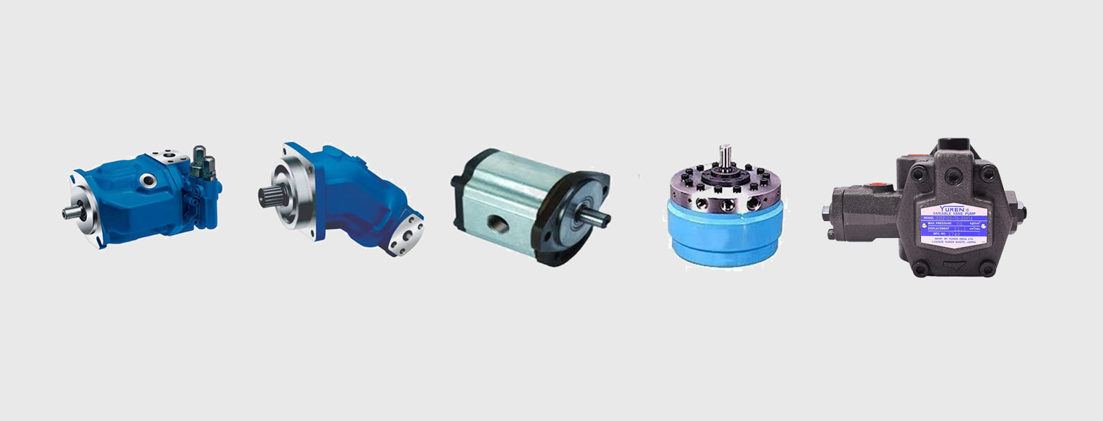
Hydraulic pumps are used in hydraulic drive systems and can be hydrostatic or hydrodynamic. A hydraulic pump is a mechanical source of power that converts mechanical power into hydraulic energy (hydrostatic energy i.e. flow, pressure). It generates flow with enough power to overcome pressure induced by the load at the pump outlet. When a hydraulic pump operates, it creates a vacuum at the pump inlet, which forces liquid from the reservoir into the inlet line to the pump and by mechanical action delivers this liquid to the pump outlet and forces it into the hydraulic system. Hydrostatic pumps are positive displacement pumps while hydrodynamic pumps can be fixed displacement pumps, in which the displacement (flow through the pump per rotation of the pump) cannot be adjusted, or variable displacement pumps, which have a more complicated construction that allows the displacement to be adjusted. Hydrodynamic pumps are more frequent in day-to-day life. Hydrostatic pumps of various types all work on the principle of Pascal's law.



Gear pumps have very few moving parts, work smoothly, and operate very well at pressures around 210 bar. It is the pump with higher speeds up to 3000-6000 rpm.
Type of gear pumps:
Hydraulic piston pumps handle very large flows at high hydraulic system pressures. Applications are mobile and construction equipment, marine, offshore and industrial.
Type of Piston Pumps:
Hydraulic vane pumps operate with much lower flow pulsation, i.e. constant flow. As such, vane pumps produce less noise while maintaining a high speed.
Type of Vane Pumps:


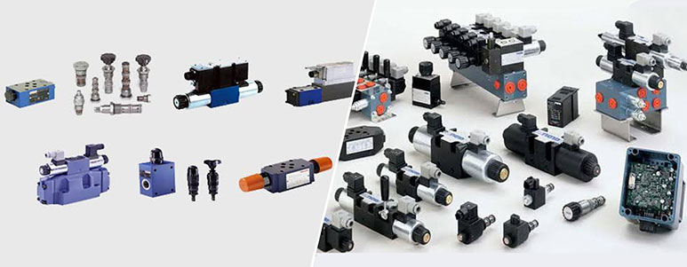
A hydraulic valve properly directs the flow of a liquid medium, usually oil, through your hydraulic system. The direction of the oil flow is determined by the position of a spool. A hydraulic system can only function - as per requirements - by using valves. Thus, you should always look for the correct type of hydraulic valve to serve your intended purpose. The required size is determined by the maximum flow of the hydraulic system through the valve and the maximum system pressure


Directional control valves can control the start, stop and change in direction of flow of a pressure medium (i.e. hydraulic oil). For this reason, they are also referred to as switching valves. Directional control valves are available as spool valves, poppet valves or rotary slide valves. Rotary slide valves, however, are no longer commonly used due to low operating pressure (up to 70 bar). Directional control valves without proportional control are referred to as switching valves.
Type of directional control valves:
Every pressure control valve switches (or controls) at a predetermined pressure setting. The switching pressure is generally a variable setting on the valve itself. A change in position of the pressure control valve (i.e. open or closed) occurs either gradually (by control) or suddenly (by switch). Pressure shut-off valves and pressure sequence valves are hydraulic valves with a fixed throttle whereas relief and reducing valves are hydraulic valves with a variable throttle.
Type of pressure control valves:
Proportional hydraulic valves are able to control the opening to flow proportionally instead of gradually, as is the case for most standard hydraulic valves. The simplest type of proportional hydraulic valve is a variable throttle controlled by a manual lever. When your hydraulic application requires a very accurate control of the flow, hydraulic valves may be equipped with advanced control electronics with integrated measuring and feedback devices.
Type of proportional control valves:
Flow control valves manage the flow by decreasing or increasing the opening at the throttling point. This helps to determine speed of movement for the hydraulic actuators. The simplest design for a flow control valve is a needle or longitudinal slot mounted in the pipeline and connected to a screw that adjusts the opening at the throttling point. These are called throttle valves due to the fixed throttle, which changes the actual flow through the valve at varying loads.
Type of flow control valves:


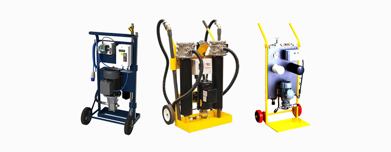
Hydraulic oil filtration unit is a compact, portable filter system designed to use at the site for contaminated oil. It is easily wheeled to the sump or reservoir by a single person. It is completely self-contained and requires only electrical connection for operation. Standard features of the unit include a reliable gear pump with an integral pressure relief valve to Prevent system over-pressure. The filter cartridge also gives high performance with minimum 200 beta ratio and can be changed in few minutes.


1. Flow rate - 20 lpm, 50 lpm, 100 lpm
2. Pressure - 10 bar
3. Design - Single stage, two stage
4. Powder coated body
5. Static pressure gauge
6. Electrical cable - 10 m
7. Inlet and outlet hose - 2 m each
8. NAS class achieved - Up to NAS 5


A hydraulic drive system is a quasi-hydrostatic drive or transmission system that uses pressurized hydraulic fluid to power hydraulic machinery. The term hydrostatic refers to the transfer of energy from pressure differences, not from the kinetic energy of the flow.
A hydraulic drive system consists of three parts: The generator (e.g. a hydraulic pump), driven by an electric motor or a combustion engine or a windmill; valves, filters, piping etc. (to guide and control the system); and the actuator (e.g. a hydraulic motor or hydraulic cylinder) to drive the machinery.


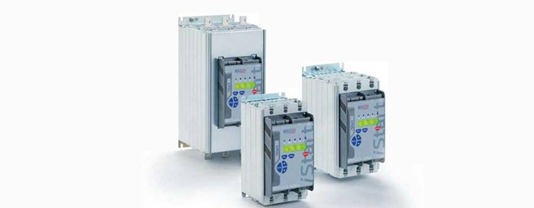
AC Motor Controllers and Drives are electronic devices that modify the input power to motors by typically adjusting the frequency of the power to the motor for the purpose of regulating the output speed and torque. Key specifications include the intended application, drive operating mode, motor type, inverter type, loop system voltage classification, power rating, communication interface, as well as input and output electrical specifications.AC motor controllers and drives are used primarily in process applications to control the speed of pumps, fans, blowers, etc. They are known as variable speed drives, adjustable frequency drives, or AC inverters. The controller, commonly integrated with the drive circuits, supplies the control signals to the drive.
DC Motor Controllers and Drives are electrical devices that modify the input power by adjusting the constant or alternating current source to a pulsed, direct current output of varying pulse duration or frequency. Key specifications include the intended application, drive operating mode, motor type, loop system, voltage classification, power rating, output signal type, communication interface, as well as input and output electrical specifications. DC motor controllers and drives are used primarily to control motor speeds and torques for machine tools, electric vehicles, pumps, etc. The controller, commonly integrated with the drive circuits, supplies the control signals to the drive.
Servo Motor Controllers and Drives are electronic devices that modify the input power by adjusting the constant or alternating current source to a pulsed, current output of varying pulse duration or frequency. Key specifications include the intended application, motor type, drive operating mode, loop system, power rating, output signal type, communication interface, as well as electrical specifications. Servo motor controllers and drives are used primarily in motion control applications in manufacturing and construction environments, among others, and used to control motor speeds, torques, and positions, and may be AC or DC driven. Servo motors are used in many applications including machine tools, micro-positioning, and robotics, among many other types of machinery, such as conveyors or spindle drive systems. The controller, commonly integrated with the drive circuits, supplies the control signals to the drive. Servo drives are also known as servomotor amplifiers.
Stepper Motor Controllers and Drives are electronic devices that modify the input power by adjusting the constant or alternating current source to a pulsed, or "stepped," current output.
Key specifications include the intended application, motor type, drive operating mode, loop system, power rating, output signal type, communication interface, as well as electrical specifications.
Stepper motor controllers and drives are used primarily in motion control applications in manufacturing and construction environments, among others, and used to control motor speeds, torques, and position. They are used in many applications including machine tools, micro-positioning, and robotics, among many other types of machinery, such as conveyors or OEM equipment. The controller, commonly integrated with the drive circuits, supplies the control signals to the drive. Stepper drives are also known as pulse drives and step amplifiers. Stepper controllers are also known as motor indexers.


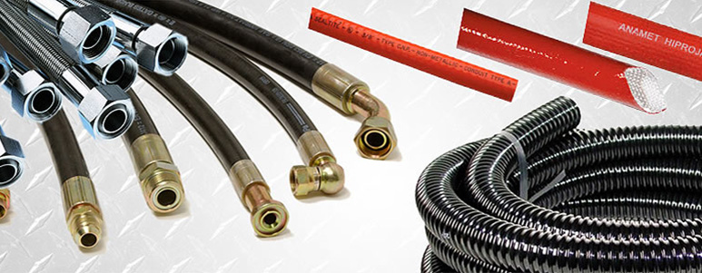
A hydraulic hose is specifically designed to convey hydraulic fluid to or among hydraulic components, valves, actuators, and tools. It is typically flexible, often reinforced, and usually constructed with several layers of reinforcement since hydraulic systems frequently operate at high or very high pressures. Hydraulic hose is used in a variety of industrial hydraulic systems. Dimensions, performance specifications, construction options, and features are important parameters to consider when searching for hydraulic hose.
Important dimensions for the selection of hydraulic hose include the inside diameter, outside diameter, and minimum bend radius. Hydraulic hose sizes are denoted by the inside and outside diameter of the hose. The inside diameter refers to the inside of the hose or liner. The outside diameter is often a nominal specification for hoses of corrugated or pleated construction. Minimum bend radius is based on a combination of acceptable hose cross-section deformation and mechanical bending limit of any reinforcement.


Single wire or double fiber braid and textile covered hydraulic rubber hoses are widely used in medium pressure applications. They are suitable for conveying petroleum-based hydraulic oil, air and water with specified pressure to air brakes, power steering, turbo oil lines and tilt cab cylinders as well as return and suction hoses of hydraulic systems.
SAE hydraulic hose, with different layers of braid or spiral wire reinforcement structures to suit all pressure working environments.
EN standard hydraulic hoses, 1SN, 2SN, 4SP and other types own different structures to be used for glycol, oil , fuel and other hydraulic fluids.
EN standard hydraulic hoses, 1SN and 2SN, own single or double braid reinforcement structures to be used for glycol, oil, fuel and other hydraulic fluids.
We supply low pressure hydraulic hoses in different sizes and dimensions. And they are anti-corrosive, durable and at a low price
Single or double braid of high tensile steel wire reinforcement with smooth or fabric cover surface supply high pressure tolerance for liquid conveying.
Several spiral wire hydraulic hoses are offered which including four spiral wire hydraulic hose, multi-spiral hose and spiral wire reinforced hydraulic hose.
Thermoplastic hydraulic hose has a promising future and it is widely used in construction equipment and hydraulic equipment in recent years.
Our standard high pressure hydraulic hose 1SN can in -40°C to +100°C, ID 4.8–50.8mm, OD 11.8–64mm, operating pressure 40–250, burst pressure 160–1000 bar.


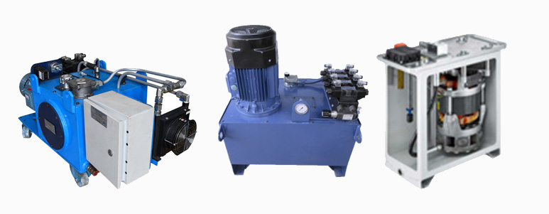
Hydraulic power packs are stand-alone devices, as opposed to a built-in power supply for hydraulic machinery. Some power packs are large, stationary units and others are more portable. They have a hydraulic reservoir, which houses the fluid, regulators that allow users to control the amount of pressure the power pack delivers to a valve, pressure supply lines and relief lines, a pump and a motor to power the pump.


Wide Options Of Accessories Which Includes Coolers, Oil Pan, Terminal Box, Manifold Block, And More.
Use Of YUKEN Variable Displacement Pump Means High Efficiency, Low Noise, Low Heat Generation. Easy To Build Circuits
Most Of The Standard Circuits Could Be Configured Using YUKEN Modular Range Of Valves
Standardization Of Components And Mass Production Method Adopted. This Means Lower Cost And Faster Delivery
Option To Add Inverter Control For Energy Saving


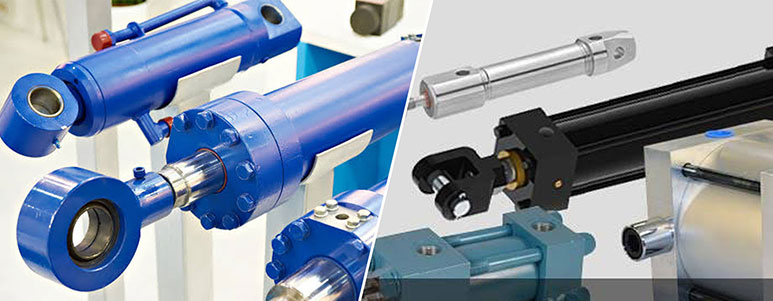
A hydraulic cylinder (also called a linear hydraulic motor) is a mechanical actuator that is used to give a unidirectional force through a unidirectional stroke. It has many applications, notably in construction equipment (engineering vehicles), manufacturing machinery, and civil engineering.


This single-acting cylinder only has a head-end port and is operated hydraulically in one direction. When oil is pumped into a port, it pushes on a plunger, causing it to extend.
The return or retraction is effected by draining the hydraulic oil back into a reservoir. The plunger will fall, or return, because of the weight of a load or else induced by an additional mechanical force such as a spring.
The Double-Acting Cylinder must have ports at both the head and rod ends. The piston is moved by pumping oil into the head which moves the piston to extend a rod. Any oil in the rod end is pushed out into a reservoir. To retract the rod, the oil flow at both ends is reversed.
A nondifferential cylinder has a piston rod extending from each end. Thrust and speed are equal in both directions, provided that pressure and flow are stable.
The cushioned cylinder is designed to slow an action and prevent shock loading at the end of a piston stroke. This cushion effect is created by building a limiting or metering device into the cylinder to restrict the flow at the outlet port which slows down the motion of the piston.


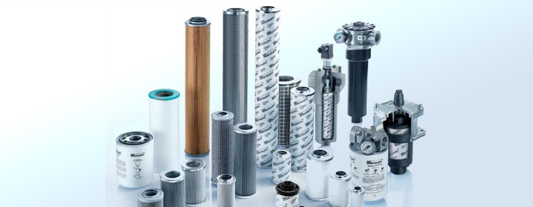
Hydraulic filters protect your hydraulic system components from damage due to contamination of oils or other hydraulic fluid in use caused by particles. Every minute, approximately one million particles larger than 1 micron (0.001 mm or 1 μm) enter a hydraulic system. These particles can cause damage to hydraulic system components because hydraulic oil is easily contaminated. Thus maintaining a good hydraulic filtration system will increase hydraulic component lifetime.


Low pressure filters operate at pressures of 10 bar or less. Suction filters are used for coarse filtration and return line filters or bypass filtration for fine filtration..
Heavy duty filtration for demanding hydraulic applications under tough conditions in continuous operation. It's flow rate is high at low to medium hydraulic system pressure.
Pressure line or standard hydraulic pressure filters are commonly used in a hydraulic system. It protects your hydraulic components against wear and tear.
Contamination control is a very important element of a hydraulic filtration system. Changing filter elements on a regular basis prevents clogging and improves oil quality.
With Par Fit you enjoy the benefits of a one-stop-shop solution for all your hydraulic filter elements of high quality at competitive prices and immediate availability.
Reservoir equipment includes components to prevent contamination as well as components to measure tank fluid level, temperature and pressure of the oil.


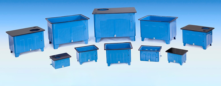
The hydraulic reservoir is a container for holding the fluid required to supply the system, including a reserve to cover any losses from minor leakage and evaporation. The reservoir can be designed to provide space for fluid expansion, permit air entrained in the fluid to escape, and to help cool the fluid.
Filling reservoirs to the top during servicing leaves no space for expansion. Most reservoirs are designed with the rim at the filler neck below the top of the reservoir to prevent overfilling. Some means of checking the fluid level is usually provided on a reservoir. This may be a glass or plastic sight gauge, a tube, or a dipstick. Hydraulic reservoirs are either vented to the atmosphere or closed to the atmosphere and pressurized.


A vented reservoir is one that is open to atmospheric pressure through a vent line. Because atmospheric pressure and gravity are the forces which cause the fluid to flow to the pump, a vented reservoir is mounted at the highest point in the hydraulic system. Air is drawn into and exhausted from the reservoir through a vent line. A filter is usually installed in the vent line to prevent foreign material from being taken into the system.
A pressurized reservoir is sealed from the atmosphere. This reservoir is pressurized either by engine bleed air or by hydraulic pressure produced within the hydraulic system itself. Pressurized reservoirs are used on aircraft intended for high altitude flight, where atmospheric pressure is not enough to cause fluid flow to the pump.
In reservoirs pressurized by engine bleed air, the amount of air pressure is determined by an air pressure regulator–usually 10 to 15 pounds per square inch (psi) gauge.
This reservoir, or tank as it is referred to by Boeing-Vertol, is constructed of a metal housing with two internal pistons, one fixed and the other a floating piston which slides along a central tube. Attached to the floating piston is a larger tube that projects through the forward end of the tank and is calibrated to indicate FULL and REFILL fluid levels for ramp-up and ramp-down positions.


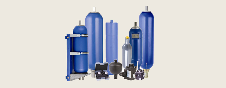
A hydraulic accumulator is a pressure storage reservoir in which a non-compressible hydraulic fluid is held under pressure that is applied by an external source of mechanical energy. The external source can be an engine, a spring, a raised weight, or a compressed gas. An accumulator enables a hydraulic system to cope with extremes of demand using a less powerful pump, to respond more quickly to a temporary demand, and to smooth out pulsations. It is a type of energy storage device.
Wherever hydraulic tasks need to be performed, hydraulic accumulators can help. They are versatile, make your machine more convenient to use, secure your hydraulic system and are used to increase the energy efficiency of hydraulic systems and for many other tasks.
Example applications include:


Bladder Accumulators consist of a welded or forged pressure vessel, the accumulator bladder and the fittings for the gas- and medium-side connection. In addition to the standard design, special designs for particular applications are possible, for example for very high discharge speeds and high pressures.
Bladder Accumulators have the following advantages:
Piston Accumulators are comprised of a cylinder with a finely processed interior, with screwed-in cover on the gas and fluid side as a rule and a piston with special sealing systems. Piston accumulators can be adjusted very flexibly to customer requirements (e.g. series SK280 with patented design). Selection of the volume is practically stepless. The piston position can be made visible and also be used for switching functions in the hydraulic system.
Piston Accumulators have the following advantages:
Diaphragm Accumulators are designed thereby either as welded constructions or as cartridge constructions and offered in various different steels, elastomers and with different gas connections.
Diaphragm Accumulators have the following advantages:
Metal bellows Accumulators are versatile in their application. For example, they are used for pulsation damping on heavy diesel engines or in the chemical industry. In the aeroplane industry, this type of accumulator design is usually used as energy accumulators or for volumetric compensation, respectively
Hydraulic Dampers have the following advantages:
Bladder, piston and diaphragm accumulators are the best-known types of accumulators. Customer-specific, industry-specific and market-specific further developments and new developments are being pushed permanently and continuously, including such special designs as spring-charged and lightweight accumulators. As a result, we can offer special accumulator technology solutions which are optimally tailored to individual cases, including complete system solutions, in addition to the comprehensive standard program.
Special applications often make special demands with respect to pressure, volume, energy, separation element, elastomers and accumulator material.
The modular design of the accumulator stations enables to incorporate all customer requirements precisely. Taking the customer's own operating data into account, we can calculate the required volumes for you and simulate the accumulator operation on the PC.
To protect your hydraulic accumulators against non-permitted temperature increase and/or excessive pressure, we recommend our safety devices.
The complete hydraulic accumulator accessory programme includes:


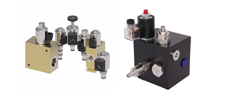
This control blocks are designed for the complex and flexible requirements in the area of lifting technology. They are tailored solutions for lifting-lowering controls which are, depending on the control block, load-dependently, load-independently or proportionately controlled. Applications include, for example, scissor-lift platforms, small lift trucks and pallet trucks. The permissible load is secured by means of an integrated pressure relief valve. The 2/2 two-way pilot valve is equipped with manual emergency lowering with self-actuating reset. A built-in return valve prevents uncontrolled lowering. A measurement connection is provided for for easy pressure measurement. In addition, a flange connection of the block to an optionally deliverable connection plate is possible.


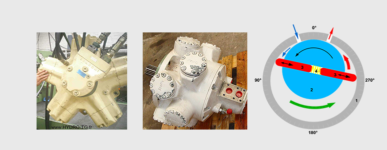
A hydraulic motor is a mechanical actuator that converts hydraulic pressure and flow into torque and angular displacement (rotation). The hydraulic motor is the rotary counterpart of the hydraulic cylinder as a linear actuator. Most broadly, the category of devices called hydraulic motors has sometimes included those that run on hydropower (namely, water engines and water motors) but in today's terminology the name usually refers more specifically to motors that use hydraulic fluid as part of closed hydraulic circuits in modern hydraulic machinery.


Radial piston motors are available in two basic types: Pistons pushing inward, and pistons pushing outward.
i. Pistons pushing inward
The crankshaft type (e.g. Staffa or SAI hydraulic motors) with a single cam and the pistons pushing inwards is basically an old design but is one which has extremely high starting torque characteristics. They are available in displacements from 40 cc/rev up to about 50 litres/rev but can sometimes be limited in power output. Crankshaft type radial piston motors are capable of running at "creep" speeds and some can run seamlessly up to 1500 rpm whilst offering virtually constant output torque characteristics. This makes them still the most versatile design.
The single-cam-type radial piston motor exists in many different designs itself. Usually the difference lies in the way the fluid is distributed to the different pistons or cylinders, and also the design of the cylinders themselves. Some motors have pistons attached to the cam using rods (much like in an internal combustion engine), while others employ floating "shoes", and even spherical contact telescopic cylinders like the Parker Denison Calzoni type. Each design has its own set of pros and cons, such as freewheeling ability, high volumetric efficiency, high reliability and so on.
ii. Pistons pushing outward
Multi-lobe cam ring types (e.g. Black Bruin, Rexroth, Hägglunds Drives, Poclain, Rotary Power or Eaton Hydre-MAC type) have a cam ring with multiple lobes and the piston rollers push outward against the cam ring. This produces a very smooth output with high starting torque but they are often limited in the upper speed range. This type of motor is available in a very wide range from about 1 litre/rev to 250 litres/rev. These motors are particularly good on low speed applications and can develop very high power.
The gerotor motor is in essence a rotor with N-1 teeth, rotating off center in a rotor/stator with N teeth. Pressurized fluid is guided into the assembly using a (usually) axially placed plate-type distributor valve. Several different designs exist, such as the Geroller (internal or external rollers) and Nichols motors. Typically, the Gerotor motors are low-to-medium speed and medium-to-high torque.
A vane motor consists of a housing with an eccentric bore, in which runs a rotor with vanes in it that slide in and out. The force differential created by the unbalanced force of the pressurized fluid on the vanes causes the rotor to spin in one direction. A critical element in vane motor design is how the vane tips are machined at the contact point between vane tip and motor housing. Several types of "lip" designs are used, and the main objective is to provide a tight seal between the inside of the motor housing and the vane, and at the same time to minimize wear and metal-to-metal contact.
A gear motor (external gear) consists of two gears, the driven gear (attached to the output shaft by way of a key, etc.) and the idler gear. High pressure oil is ported into one side of the gears, where it flows around the periphery of the gears, between the gear tips and the wall housings in which it resides, to the outlet port. The gears then mesh, not allowing the oil from the outlet side to flow back to the inlet side. For lubrication, the gear motor uses a small amount of oil from the pressurized side of the gears, bleeds this through the (typically) hydrodynamic bearings, and vents the same oil either to the low pressure side of the gears, or through a dedicated drain port on the motor housing, which is usually connected to a line that vents the motor's case pressure to the system's reservoir. An especially positive attribute of the gear motor is that catastrophic breakdown is less common than in most other types of hydraulic motors. This is because the gears gradually wear down the housing and/or main bushings, reducing the volumetric efficiency of the motor gradually until it is all but useless. This often happens long before wear causes the unit to seize or break down.


